|
|
引言
在无人机捷联导航系统中,由加速度计、角速度计、气压计、GPS、磁力计等组成了一个复杂的惯性捷联导航系统,以保证无人机的正常稳定飞行。由于涉及机体坐标系到导航坐标系的变换,以及状态间的耦合关系,导致无人机飞控捷联导航系统构成了一个复杂的非线性动态系统,以速度估计为例,速度更新方程就是一个非线性状态方程。而利用Kalman滤波进行状态最优估计的一个重要前提便是应用对象为线性系统,在最优估计时必然会涉及到线性化的处理。
T_{b}^{n}=\begin{bmatrix} q_{0}^2 + q_{1}^2 - q_{2}^2 - q_{3}^2 & 2*(q_{1}*q_2 - q_{0}*q_3) & 2*(q_1*q_3 + q_0*q_2)\\ 2*(q_1*q_2 + q_0*q_3) & q_0^2 - q_1^2 + q_2^2 - q_3^2 & 2*(q_2*q_3 - q_0*q_1) \\ 2*(q_1*q_3-q_0*q_2) & 2*(q_2*q_3 + q_0*q_1) & q_0^2 - q_1^2 - q_2^2 + q_3^2 \end{bmatrix}
% define the velocity update equations
% ignore coriolis terms for linearisation purposes
vNew = [vn;ve;vd] + [0;0;gravity]*dt + Tbn*dVelTruth;在进行EKF的飞控系统之前,可在PX4官网下载其导航代码。其下载地址如下,若有兴趣的话,也可把其他代码全部下载到本地。
PX4/ecl
一、捷联导航系统线性化
1.1 状态模型
状态预测方程:
stateVectorNew = F*stateVector + Q
观测方程:
Y=H*stateVector + R
——————————————————
stateVectorNew\Rightarrow 24个状态更新向量
stateVector\Rightarrow 24个状态向量
F\Rightarrow 状态转移矩阵 H\Rightarrow 观测方程
Q\Rightarrow 过程噪声 R\Rightarrow 测量噪声
——————————————————
其中, stateVectorNew 与 stateVector 的定义如下所示:
% Define the state vector & number of states
stateVector = [quat;vn;ve;vd;pn;pe;pd;dAngBias;dVelBias;magN;magE;magD;magX;magY;magZ;vwn;vwe];
% Define vector of process equations
stateVectorNew = [quatNew;vNew;pNew;dAngBiasNew;dVelBiasNew;magNnew;magEnew;magDnew;magXnew;magYnew;magZnew;vwnNew;vweNew];1.2 导航系统模型的线性化
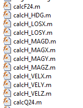
在导航工程(\EKF_replay\Filter)中,下面的文件给出了状态转移方程 F 及各观测方程 H 的数学模型,单纯地看这些方程,十分复杂,那怎么计算出来呢?

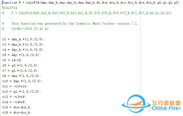
状态转移矩阵文件:\EKF_replay\Filter\calcF24.m

通过\ecl\EKF\matlab\EKF_replay\Filter\GenerateEquations24.m文件可知,该文件构建了飞控导航系统的模型,利用各状态间的数学模型以及前篇的《涅索斯衬衫:扩展卡尔曼滤波(EKF)之非线性系统的线性化》方法,即可求解上述各捷联导航系统的线性化模型。其部分源码如下所示:
%% define the state prediction equations
% define the measured Delta angle and delta velocity vectors
dAngMeas = [dax; day; daz];
dVelMeas = [dvx; dvy; dvz];
% define the IMU bias errors and scale factor
dAngBias = [dax_b; day_b; daz_b];
dVelBias = [dvx_b; dvy_b; dvz_b];
% define the quaternion rotation vector for the state estimate
quat = [q0;q1;q2;q3];
% derive the truth body to nav direction cosine matrix
Tbn = Quat2Tbn(quat);
% define the truth delta angle
% ignore coning compensation as these effects are negligible in terms of
% covariance growth for our application and grade of sensor
dAngTruth = dAngMeas - dAngBias;
% Define the truth delta velocity -ignore sculling and transport rate
% corrections as these negligible are in terms of covariance growth for our
% application and grade of sensor
dVelTruth = dVelMeas - dVelBias;
% define the attitude update equations
% use a first order expansion of rotation to calculate the quaternion increment
% acceptable for propagation of covariances
deltaQuat = [1;
0.5*dAngTruth(1);
0.5*dAngTruth(2);
0.5*dAngTruth(3);
];
quatNew = QuatMult(quat,deltaQuat);
% define the velocity update equations
% ignore coriolis terms for linearisation purposes
vNew = [vn;ve;vd] + [0;0;gravity]*dt + Tbn*dVelTruth;
% define the position update equations
pNew = [pn;pe;pd] + [vn;ve;vd]*dt;
% define the IMU error update equations
dAngBiasNew = dAngBias;
dVelBiasNew = dVelBias;
% define the wind velocity update equations
vwnNew = vwn;
vweNew = vwe;
% define the earth magnetic field update equations
magNnew = magN;
magEnew = magE;
magDnew = magD;
% define the body magnetic field update equations
magXnew = magX;
magYnew = magY;
magZnew = magZ;
% Define the state vector & number of states
stateVector = [quat;vn;ve;vd;pn;pe;pd;dAngBias;dVelBias;magN;magE;magD;magX;magY;magZ;vwn;vwe];
nStates=numel(stateVector);
% Define vector of process equations
stateVectorNew = [quatNew;vNew;pNew;dAngBiasNew;dVelBiasNew;magNnew;magEnew;magDnew;magXnew;magYnew;magZnew;vwnNew;vweNew];
%% derive the state transition and state error matrix
% Define the control (disturbance) vector. Error growth in the inertial
% solution is assumed to be driven by 'noise' in the delta angles and
% velocities, after bias effects have been removed. This is OK becasue we
% have sensor bias accounted for in the state equations.
distVector = [daxVar;dayVar;dazVar;dvxVar;dvyVar;dvzVar];
% derive the control(disturbance) influence matrix
G = jacobian(stateVectorNew, [dAngMeas;dVelMeas]);
% derive the state error matrix
distMatrix = diag(distVector);
Q = G*distMatrix*transpose(G);
f = matlabFunction(Q,'file','calcQ24.m');
% derive the state transition matrix
F = jacobian(stateVectorNew, stateVector);
f = matlabFunction(F,'file','calcF24.m');
%% derive equations for fusion of magnetometer measurements
% rotate earth field into body axes
magMeas = transpose(Tbn)*[magN;magE;magD] + [magX;magY;magZ];
magMeasX = magMeas(1);
H_MAGX = jacobian(magMeasX,stateVector); % measurement Jacobian
f = matlabFunction(H_MAGX,'file','calcH_MAGX.m');
magMeasY = magMeas(2);
H_MAGY = jacobian(magMeasY,stateVector); % measurement Jacobian
f = matlabFunction(H_MAGY,'file','calcH_MAGY.m');
magMeasZ = magMeas(3);
H_MAGZ = jacobian(magMeasZ,stateVector); % measurement Jacobian
f = matlabFunction(H_MAGZ,'file','calcH_MAGZ.m');
%% derive equations for fusion of synthetic deviation measurement
% used to keep correct heading when operating without absolute position or
% velocity measurements - eg when using optical flow
% rotate magnetic field into earth axes
magMeasNED = [magN;magE;magD];
% the predicted measurement is the angle wrt magnetic north of the horizontal
% component of the measured field
angMeas = atan(magMeasNED(2)/magMeasNED(1));
H_MAGD = jacobian(angMeas,stateVector); % measurement Jacobian
H_MAGD = simplify(H_MAGD);
f = matlabFunction(H_MAGD,'file','calcH_MAGD.m');
%% derive equations for fusion of a single magneic compass heading measurement
% rotate body measured field into earth axes
magMeasNED = Tbn*[magX;magY;magZ];
% the predicted measurement is the angle wrt true north of the horizontal
% component of the measured field
angMeas = atan(magMeasNED(2)/magMeasNED(1));
H_MAG = jacobian(angMeas,stateVector); % measurement Jacobian
f = matlabFunction(H_MAG,'file','calcH_HDG.m');通过该文件计算相应的线性模型后,根据当前的标称轨迹,求解出领域内的线性化模型。利用卡尔曼滤波方法,即可进行状态的最优估计。如磁力计融合为例(\ecl\EKF\matlab\EKF_replay\Filter\FuseMagnetometer.m)。
% calculate the observation jacobian, innovation variance and innovation
for obsIndex = 1:3
% Calculate corrections using X component
if (obsIndex == 1)
H(1,:) = calcH_MAGX(magD,magE,magN,q0,q1,q2,q3);
elseif (obsIndex == 2)
H(2,:) = calcH_MAGY(magD,magE,magN,q0,q1,q2,q3);
elseif (obsIndex == 3)
H(3,:) = calcH_MAGZ(magD,magE,magN,q0,q1,q2,q3);
end
varInnov(obsIndex) = (H(obsIndex,:)*P*transpose(H(obsIndex,:)) + R_MAG);
innovation(obsIndex) = magPred(obsIndex) - magMea(obsIndex);
end二、飞控导航系统仿真
按照\EKF_replay\readme.txt的方式对实飞数据进行格式转化,并存放在相应的目录内。当然,若没有实飞数据,则可直接下载官网的飞行测试数据进行算法的仿真测试即可。
- 将\ecl\EKF\matlab\EKF_replay\Filter设为当前路径。
- 根据实际的飞控条件,配置相应的系统参数.\EKF_replay\SetParameters.m。
- 根据实际的测试数据类型(PX4或APM的数据),运行.\EKF_replay\replay_apm_data.m文件或.\EKF_replay\replay_px4_data.m文件。
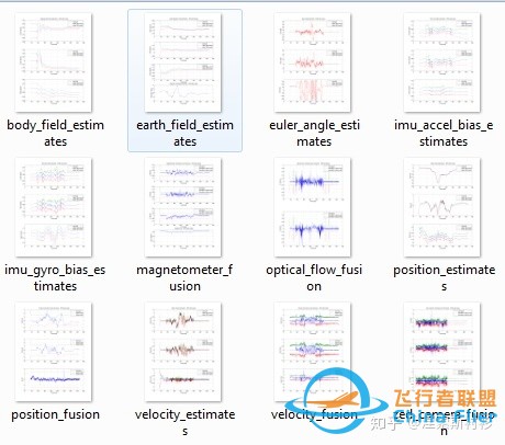
- 当运行完成后,文件夹OutputPlots即可查看导航测试结果。如下所示:

三、飞控导航系统的文件转化
起初,若直接看EKF飞控源码的话,可能会被其中的矩阵式的表示方式直接吓到。如估计误差协方差矩阵的求取(\ecl\EKF\covariance.cpp),实际上状态转移矩阵、观测矩阵以及协方差矩阵都是由matlab文件直接转化而来。详情可查看如下文件:
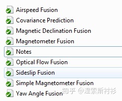
\ecl\EKF\matlab\scripts\Inertial Nav EKF\GenerateNavFilterEquations.m

参考文献
[1] Robot Localization and Kalman Filters
[2] PX4: ROS with Gazebo Simulation
<hr/> |
|